.:: Type-E Pulse Forming Network Optimization ::.
Type-E Pulse Forming Network Optimization
LAST MODIFIED: 11-10-2021 | PAGE HITS: 3,366
Introduction:
This project is aimed at the design of a new bread of type-e pulse forming networks (PFN). Today's type-e PFNs used in radar equipment use many meshes of capacitors with inductors in order to achieve a smooth flat pulse. My design uses infinite meshes since there is mutual inductance per capacitance and the total inductance and capacitance are set to what is calculated for a regular PFN. Basically it is a metallic tube with a dielectric around it and wire around it. Wire vs. core acts as the capacitor and the coil as the inductor. This will require lots of optimization since both capacitance and inductance will share some of the same dependant variables. Wire diameter, core diameter, dielectric width, dielectric constant, inductor core constant, distance between wire and core, etc... these will all need to be optimized so that both inductance and capacitance can be set to the desired values. I have divided this project into different parts for the sake of organization. The parts are for now assigned as the following.
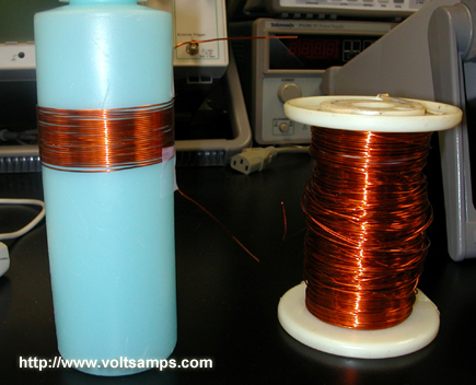
Part 01 - Testing validity and error of the air core inductor formula
Part 02 - Writing radial PFN optimization software
Part 03 - Choosing dielectric and suitable dimesnsions
Part 04 - Construction
Part 05 - Testing
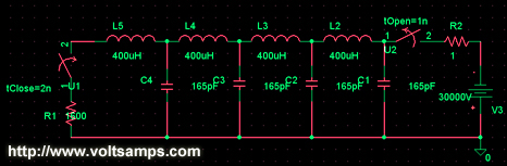
This is a standard type-e PFN schematic with 4 meshes. This PFN was designed to provide a 2uS pulse through a 1600 Ohm characteristic impedence, which is what is needed in order to power a 2J56 50kW X-Band pulsed magnetron. The radial PFN project will be designed for the same values in order to demonstarte that it is practical for real world applications, such as radar.
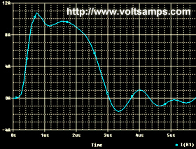
This is the graph of the current through the impedence, R1, in the above schematic. As you can see the output pulse is relatively flat. The reason for the wave-like behavior and initial current overshot is because there are only 4 meshes in the above circuit. The radial PFN will act as infinite meshes and should thus have a flatter pulse.
Part 01: (Testing validity and error of the air core inductor formula)
Materials:
- Copper Wire
- Coil Form
- LCR Meter
- Ruler
Procedure:
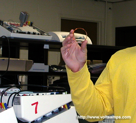
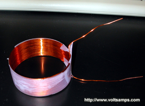
- Wind wire around a non ferrous coil form
- Measure the length of the coil
- Measure the diameter of the coil
- Count the turns
- Calculate the theoretical value using Wheeler's Formula
L = ((d * n) ^ 2) / ((18 * d) + (40 * l))
Where:
L = Inductance (uH)
d = Diameter of coil from center of wire to center of wire (inch)
n = Number of turns
l = Length of coil from one side to the other (inch)
Data:
Part01:
d = 52.4mm = 2.06"
n = 27
l = 19.5mm = .768"
L = ((2.06 * 27) ^ 2) / ((18 * 2.06) + (40 * .768)) = 45.6
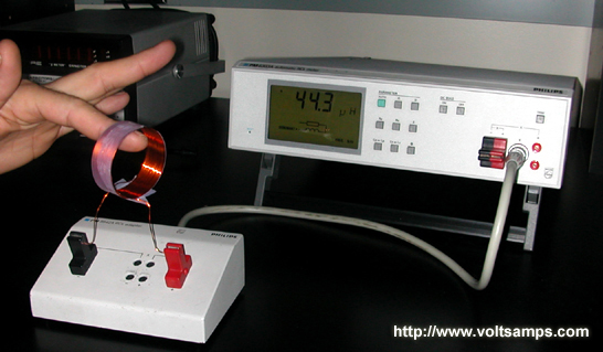
L (calculated) = 45.6uH
L (measured) = 44.3uH
Error = 2.9%
Conclusion:
The low percent error was a result of high quality construction and an accurate formula. I can safely use this formula in the PFN optimization application.
Part 02: (Writing radial PFN optimization software)
Materials:
- Computer
- Visual Basic 6.0
Procedure:
(Too many unrelated details)
Data:
Conclusion:
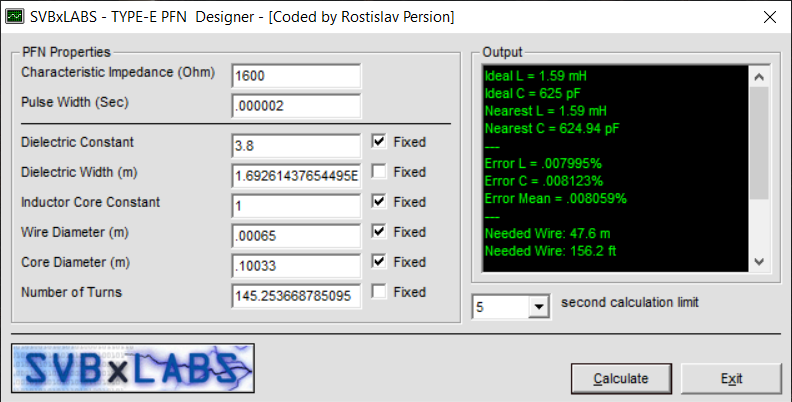
The software works very well and optimized the variables very quickly and down to .0003% error, which is much less than I can even construct it at. I designed the app to use a genetic algorithm so that I can optimize the variables with any variable(s) set as fixed. This is useful because if I purchase a pipe of a specific diameter and cannot change this variable then I can set it as fixed and optimize for other variables with stunning accuracy.
Part 03: (Choosing dielectric and suitable dimesnsions)
Description:
This part of the project requires that I select a propper dielectric material for the core coating. I chose to work with epoxy resin because it is easy to apply and machine. In order to continue on with the project I would need to measure the dielectric constant of the epoxy so that I can go on and optimize for other variables.
Materials:
- 2, 5.1cm x 20cm aluminum plates
- #19 x 1/2" nails
- Epoxy Adhesive (Extra Setting Time)
- Precision LCR meter
- Vernier
Procedure:
- Measure the exact width and length of the two metal plates
- Calculate the area of one of the plates
- Measure diameter of nails
- Use nails to space out the plates
- Calculate the theoretical vacuum capacitance of the capacitor
- Pour epoxy between the plates making sure no air bubbles remain
- Allow the two parallel plates to dry
- Using the LCR meter, measure the exact capacitance of the plates
- Divide the actual value by the theoretical vacuum capacitance to get the dielectric constant
Data:
The aluminum bars after being cut from a larger piece.
The epoxy was applied and the plates pressed together.
Close view of the spacer holding the plates a constant distance apart.
This is the precision LCR meter that I used for my measurements.
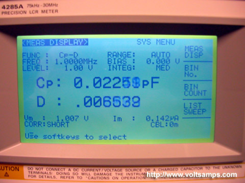
The read out with no capacitance attached.
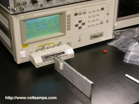
The aluminum plates with epoxy dielectric in between.
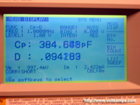
The capacitance read out of the epoxy capacitor.
Conclusion:
Having measured the plate dimensions the area turned out to be 10200mm^2. Then I measured the diameter of the spacer nails I used and got a value of 0.93mm. After calculating the theoretical capacitance of 97pF I went ahead and measured the actual epoxy capacitor with an LCR meter and found it to be 385pF. Being limited to two significant figures the dielectric constant came out to be 4.0.
Part 04: (Construction)
Materials:
- Aluminum tube
- 22AWG wire
- 1/4 gallon of epoxy resin and hardener
Procedure:
[03/07/03]
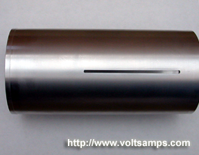
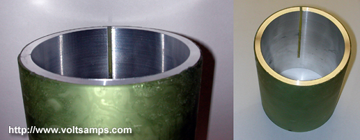
The aluminum tube for the coil form went through its initial machining stages (pre-dielectric). The tube was lathed to a specified diameter and a slit was placed in the side for eddy current reduction. Extra tubing was left on the coil form so that it can be reinserted in the lathe once more for precise machining of the epoxy dielectric coating.
[03/25/03]
The epoxy has finally hardened after a long period of waiting (due to improper resin to hardener ratios). The entire setup, aluminum and epoxy combination, have been brought back to the machine shop once again for machining the epoxy down to 1.692mm. I hope the machine work is completed soon since my project dead-line is approaching quickly. I have yet to construct a proper coil around the dielectric. Then I still have to test the PFN output and compare it with my theoretical output.
[03/31/03]
The epoxy dielectric has been machined and the inner area of the core has been cleaned out. I also wrapped 22AWG wire around the dielectric. The visual apearance is all thats left to do. Great thanks to Walter and Jeff who machined this thing for me.
Data:
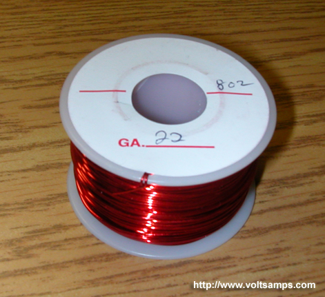
Here is the 22AWG wire which I will be using. I will have much wire left over after making the coil.
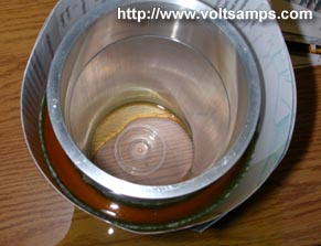
The core sits uncompleted. It has yet to be convered in a thick layer of epoxy and then machined down. After that the long end will be cut off. Te reason for it being there now is so that the lathe at the machine shop can regrip the tube exactly as it did before for a very high precision cut.
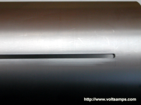
An upclose of the tube's side reveals the slit which will prevent eddy currents in the core. The width of the slit compared to the circumfrance of the tube is so small that it will not affect capacitance much at all.
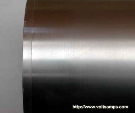
The edge of the tube is a bit larger in diameter and gives a glimpse of what the tube originally looked like before being lathed to spec.
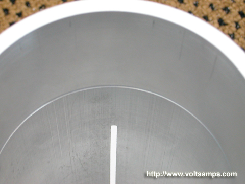
The inside of the tube was machined as well so that the tube can be placed on the lathe again with high precision for its future epoxy lathing step.
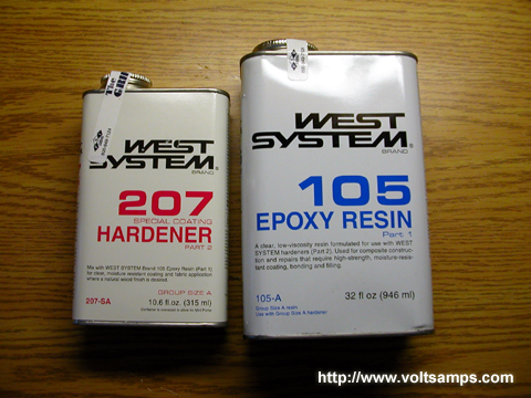
This is epoxy resin #105 with #207 hardener. After curing it should apear semi-transparent with a slight yellow tint.
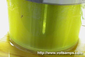
I used a CDR container cover as my mold container for the epoxy. You can see the PFN through the yellow epoxy.
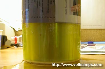
Above the CDR cover I used paper to further extend the epoxy mold enclosure.
A top view shows the thickness of the epoxy. By touching the aluminum you get an idea of how much heat is produced during the chemical reaction between the resin and hardener. The temperatures get high enough to even melt through packaging tape!
The PFN dielectric is completed after machine work and turned out quite good despite some non-hardened epoxy areas.
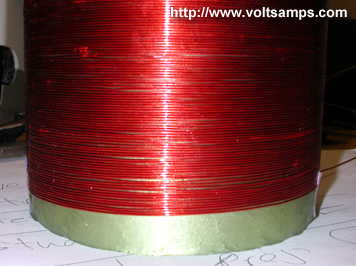
The 22AWG wire was wrapped around the core dielectric and the ends secured with scotch tape temporarily.
Conclusion:
Construction went as planned with the exception of some minor chemical blunders in the epoxy hardening process. All that is left to do, as far as construction goes, is the outter visual appearance. Next is testing.
Part 05: (Testing)
Materials:
- 100MHz O-Scope
- Bench power supply
- Resistive dummy load
- PFN
Procedure:
- Charge the PFN using the bench power supply
- Discharge the PFN into O-Scope monitored dummy load
Data:
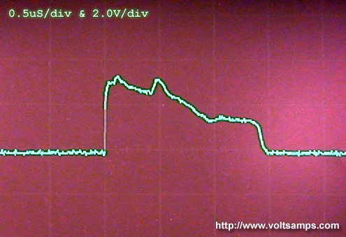
This is the O-Scope output from a PFN discharge.

A theoretical prediction is layed over the actual output. You can see some differences which are the result of the epoxy blunder. Because the epoxy didn't completely harden on one location the wire wrapped around the dielectric had sunk in and raised the capacitance in that location.
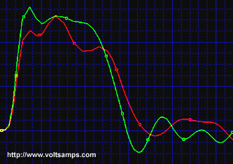
I simulated the same localized capacitive increase which caused the pulse shape difference and my simulated result confirmed this theory.

In the simulation I icreased the second to last capacitor value by a factor of approximatly teo to simulate the wire sinking into the epoxy half way twards the end of the PFN.
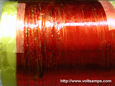
Here you can see the physical deffect.
Conclusion:
Overall this experiment was a success in demonstrating the functionality of a radial style type-e PFN. The next step would be to attempt the use of higher magnetic permeability core to reduce the PFN size by a huge amount.